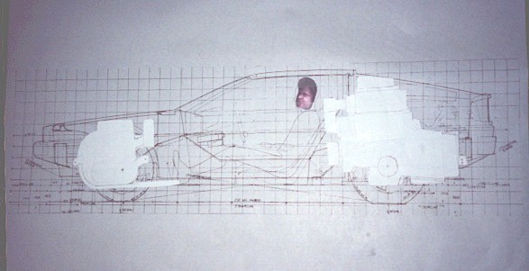
 Before I was willing to start cutting the Delorean into tiny pieces, I had to really convince myself that both new engines could be crowbarred in. To do this, I made detailed measurements of the two engines, and made scaled paper cutout models of them to paste on an equally scaled drawing of the car. Low tech, and very effective. It showed that everything would, or at least could, fit - barely. Check out the paperdoll of the rear drivetrain. It has a paperdoll blower, with paperdoll pulleys. I originally intended to supercharge both engines, but decided against it. I might pick that thought up again, at a later date. The disembodied head (me) is proof positive that after enough diet-cola-beverage-products, it can in fact seem like a good idea to stick your head on a scanner bed and take a smooshed picture of yourself.
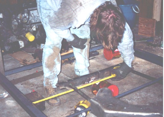
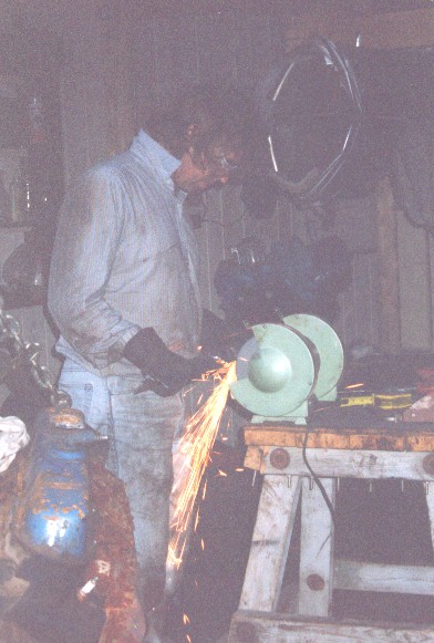 Grinding the crossbeam welds. This piece was taken from the 1985 Eldorado, and altered to adapt to the new frame.
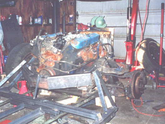
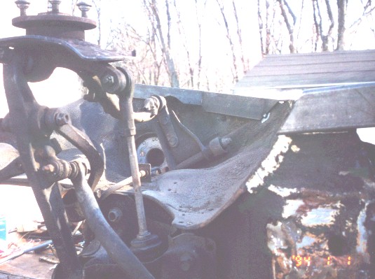
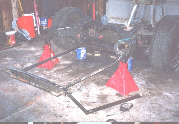 Here is the crossbeam, accurately located, but floating in air waiting for the rest of the frame. At the back of the engine cradle, you can see the square tubing transmission brace, which is custom made to interface the 1970 engine to the 1985 frame rails. The sizes of the various members were carefully selected to withstand the expected forces.
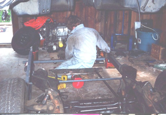 Placement of the side rails. Positioning of these parts was pretty critical, or the car would be crooked in some fashion. The target accuracy of anything I considered "critical" was 1/8inch. The positioning of most of the frame parts, tacking, remeasuring, checking again, was a very time-consuming process. Coffee cans as supports were annoying. 5-1/8 inch wooden blocks I made later, corresponding in height to the design ground clearance, were much better.
 Measurements for the attachment of the torsion bar crossbeam to the side rails, which in this photo are temporarily tacked in position.
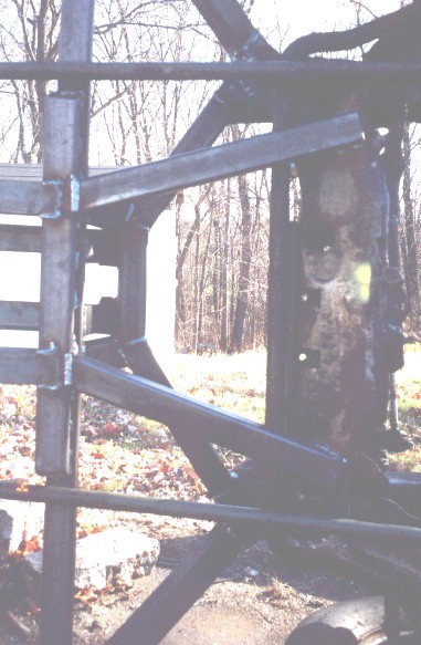
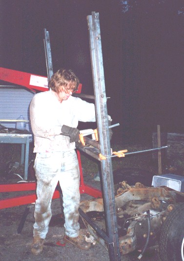 Clamping up the heavily reinforced and extended crossbeam to the side rails prior to welding. The side rails are vertical in this picture.
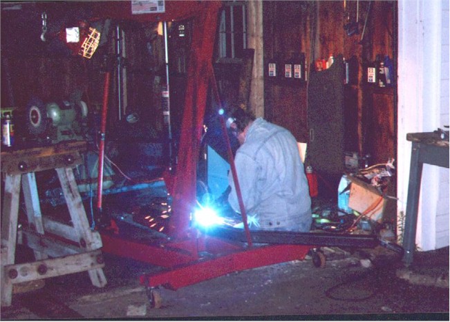 The welding was done with a Millermatic 185 welder, which will weld up to 1/2 inch plate in a single pass per side, and still run off a household stove/drier circuit.
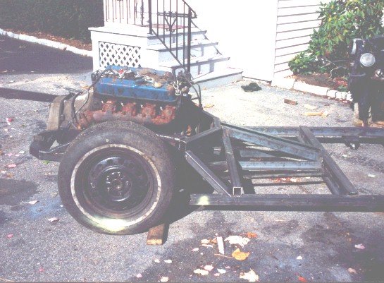
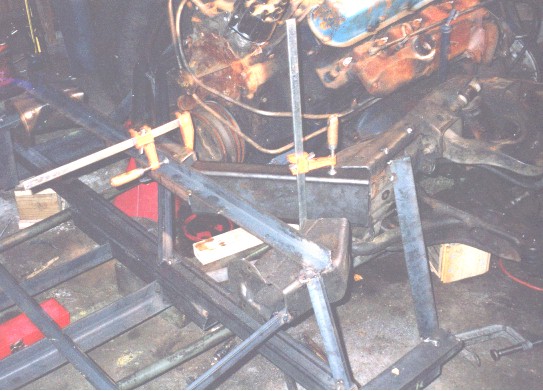 The frame is coming along nicely. I felt pretty good about the 2"by5"by3/16" wall thickness transverse beam being assembled in front of the rear engine. Attaching this piece to the 1985 frame rails was time-consuming, as the 1985 Eldorado frame rails had to be cut away on both sides of the beam, while not disturbing any of the temporary supports. At this stage of development, the frame seems to have at least as many temporary support pieces maintaining the dimensions, as actual components.
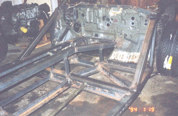
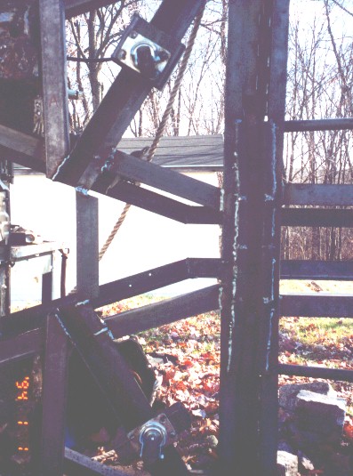
 The transverse beam is tacked in place, the side rails are connected together, the bottom of the center section is in place. The rear portion of the frame is not permanently connected to the center portion at this time. The only connections are the two torsion bars, and the five visible temporary members. The shock absorbers have been removed and temporary steel members have been tacked in their place to lock the suspension at the expected "loaded" location.
 The rear and center portions of the frame are connected to each other now. The sloped diagonal members eventually had to go. They're in the way of the position of the fuel tank. Everywere I could, I tried to arrange the frame members so their vertices formed tetrahedrons, to maximize the strength of the frame. Sometimes constraints prevented that, but overall I'm very satisfied with the rigidity of the new frame. The yellow spraypainted portion of the side rail gets cut off at a later time. The yellow spraypaint blobs are undoubtedly overspray from the line painting.
 After a few days of sheetmetal cutting, I had trimmed away all parts of the Prelude front end that were in the way, or were non-structural. It was desirable to make the front as small as possible, to allow as much of the composite underbody of the Delorean as possible to remain unremoved. The attachment of the Prelude front end to the center portion of the new frame was the most technically demanding part of the construction of the frame. Though the sheetmetal of the Prelude is plenty strong enough to hold the Prelude together as a Prelude, once I started cutting away portions, it was comparatively flexible. All sorts of hidden reinforcements are connecting the Prelude front end to the center portion of the frame. The center portion is kind of starting to look like a Delorean frame.
All in all, this section took several weeks.
After a few days of sheetmetal cutting, I had trimmed away all parts of the Prelude front end that were in the way, or were non-structural. It was desirable to make the front as small as possible, to allow as much of the composite underbody of the Delorean as possible to remain unremoved. The attachment of the Prelude front end to the center portion of the new frame was the most technically demanding part of the construction of the frame. Though the sheetmetal of the Prelude is plenty strong enough to hold the Prelude together as a Prelude, once I started cutting away portions, it was comparatively flexible. All sorts of hidden reinforcements are connecting the Prelude front end to the center portion of the frame. The center portion is kind of starting to look like a Delorean frame.
All in all, this section took several weeks.
 Flipping the frame on its side allowed easier welding of the bottom of the frame. The fronts of the Prelude rails are still cut to a random length in this picture.
 Here's a view from below of the connection of the center portion of the frame to the rear portion, which came from the front end of the 1985 Eldorado. The torsion bars and anti-sway bar are visible in this picture.
 Getting ready to interface the front end to the center portion. Scraping away the undercoating prior to welding was a pain.
 Finish-welding all the tacked joints. If it's wrong now, it's staying wrong, unless it's really really wrong. I got a lot of mileage out of those little casters.
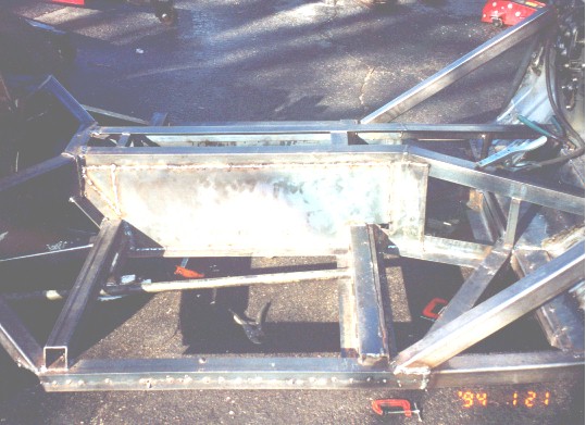 Welding in the sides of the center beam. The square opening near the welding ground clamp is the access door to the storage area, which is located in the position the fuel tank occupies in a normal Delorean. Because the center beam houses the new fuel tank, the center beam was designed and welded with extra care. It's airtight on the top and sides, and fabricated out of heavy steel plate. It's practically bulletproof. I was thinking of rollovers when I designed it.
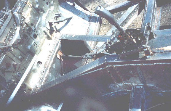 Trial fitting the shift cabling and weld-up of the shift lever mounts.
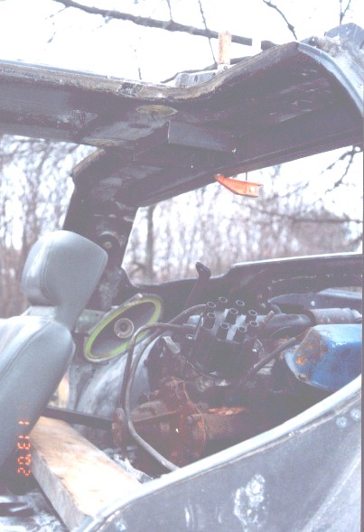 I had decided early on that there would be a non-structural, medium guage rear firewall between the rear engine and the underbody. As I got ready to fabricate it, it occurred to me that by making the outline of it out of heavier tubing, that it could double as a roll-bar, and as a roof reinforcement. It always pleased me when improvements just sort of suggested themselves like that, without me having to think about them on purpose. Here's a picture of the top part of the roll bar, as yet unattached to anything else other than being clamped to the roof support for location. I put the seat in position to get a feel for how much room there would be between the engine and the firewall and underbody. There was actually more room than I expected, something that didn't happen very often.
 Here is the addition of the rear impact absorber mount. I didn't have to think much; just copy the original design from the Delorean frame.
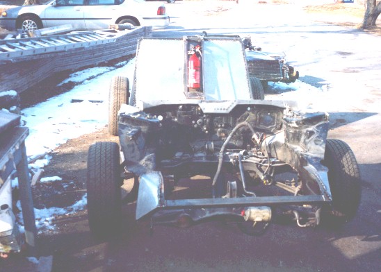 Just about done. The rear firewalls are in. The crudely cut front end has been finished off. A sheet metal flange was welded to the top of the front firewall to clean up the joint between the frame and the underbody.
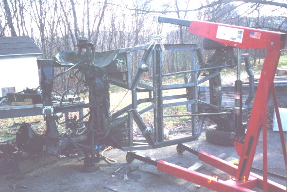
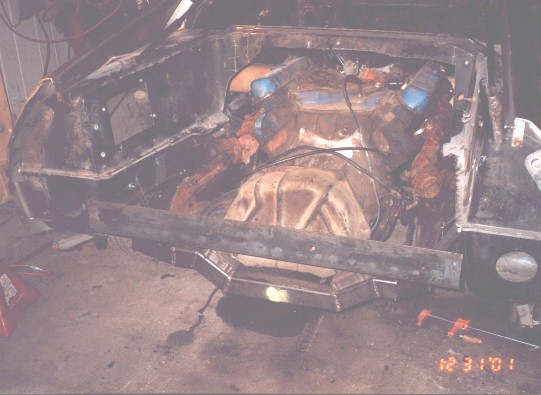
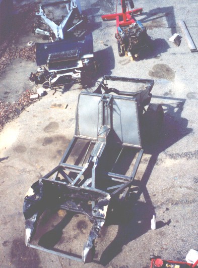 Bare frame, before painting. I like this view, because you can see a little of everything. The old frame and the 1970 Cadillac engine are in back of the new frame.
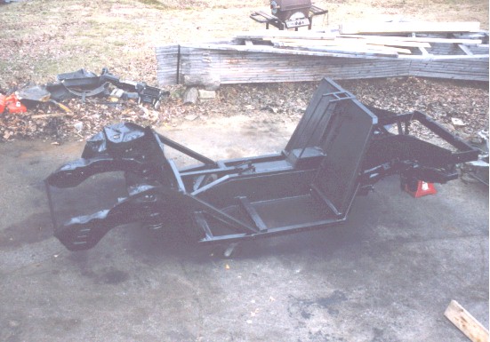 The bare frame, painted, and essentially complete. This point in time was interesting to me, in that after it, I had to put on clean clothes to work on the car. I was unaccustomed to that.
 Forward to the Underbody.
 Back to Index.